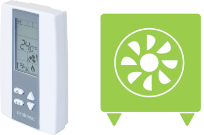
A World of Possibilities
Heat Pump Applications Using the TUCB Series Controller
As you all may know, the Universal Controller (TUCB series) can be used for fan coil units as well as heat pumps.
The two functions are separated by a configuration named "Heat Pump Option". This configuration can be found at Binary Value 95 (BV.95)
when using BACnet or at step 9 of the Specification and Installation manual. This configuration changes the default values of the outputs on the
controller to match standard heat pump applications.

Once the heat pump option is selected, the default configurations are:
- BO1 Reversing valve
- BO2 Compressor 1 (Y1)
- BO3 Heat 1 (W1)
- BO4 High Speed Fan
- BO5 Medium Speed Fan
- BO6 Low Speed Fan
Here is a summary of the configuration possibilities;
Fan
The fan can be configured from a one (1) speed fan to three (3) speed fan. This selection is found at step 22 of the Specification and Installation manual
(MSV.25 on BACnet). Note that the heat pump does not have the option to modulate the fan (0-10Vdc). When configuring a two (2) speed fan, BO4 becomes
available for Compressor 2 (Y2). When configuring a one (1) speed fan, BO5 becomes available for Heat 2 (W2).
Reversing Valve
By default, the reversing valve is configured to be energized when in cooling mode (O).
Most heat pump manufacturers have their reversing valve set-up in this manner. If the reversing valve must be energized when in heating mode,
then simply select "B" at step 10 of the Specification and Installation manual (BV.96 on BACnet).
Emergency Heat Output(s) - W1 & W2
By default, EMH outputs (W1 & W2) are disabled and will not operate. At step 11 of the Specification and Installation manual (BV.98 on BACnet),
you may allow the emergency heat to be functional. When enabled, EMH mode becomes available along with auto, heating only, cooling only, fan and off.
When the controller is set in EMH mode (MSV.1 on BACnet or press the mode button (with a snowflake/flame icon) on the controller):
- he compressors are disabled (Y1 & Y2)
- W1 becomes the first heating stage and takes the configuration settings of Y1.
- W2 configuration settings do not change.
EMH Auto Mode
By default, "Emergency Heat Auto Mode" is disabled. This means that the EMH will only be active if EMH mode is selected. In order for the EMH to be active
automatically, change the configuration to "Enable" (step 12 of the Specification and Installation manual or BV.97 on BACnet).
Y2 Output - Enable/Disable
By default, Y2 (compressor 2) is disabled. If a 2 stage compressor is required, then simply enable this configuration (step 27 of the Specification and
Installation manual or BV.99 on BACnet).
Output Close Percentage/Open Percentage
The last step of the configuration consists of setting the activation and de-activation required for cooling and heating. If the default values are not
changed, there is a likely chance that the controller will not activate the outputs at the right time. BO1 reversing valve and fan outputs (BO4 to BO6)
cannot be changed and are set automatically. If one (1) speed fan is used, BO4 and BO5 will require a change in settings if they are used.
Compressors 1 and 2 (Y1 & Y2) should be the first two stages to be activated. If temperature drops, then W1 and W2 are energized to maintain zone temperature
setpoint.
Note that "Close Percentage" represents the percentage of the demand at which the output is energized. The "Open Percentage" represents the percentage of the
demand at which the output is de-energized. It must be viewed as contacts; Closed contact = On, Open contact = Off.
Heat Pump Examples
The following are examples of the configurations for one speed fan heat pumps. Note that only the configuration changes are shown. Any default values that are
configured in the right manner are not shown.
Heat Pump - 1 Speed Fan, 1 Compressor with 1 Stage EMH
Heat Pump - 1 Speed Fan, 1 Compressor with 2 Stage EMH
Heat Pump - 1 Speed Fan, 1 Compressor with Modulating EMH
Heat Pump - 1 Speed Fan, 1 Compressor with No EMH
Heat Pump - 1 Speed Fan, 2 Compressors with 1 Stage EMH
Heat Pump - 1 Speed Fan, 2 Compressors with 2 Stage EMH
Heat Pump - 1 Speed Fan, 2 Compressors with Modulating EMH
Heat Pump - 1 Speed Fan, 2 Compressors with No EMH